Posts

Showing posts with the label directional control valves

Working of directional control valve explained with working @JSD Enginee...

Image

Yuken check valve

Image
Check valve : Check valves are two-port valves, meaning they have two openings in the body, one for fluid to enter and the other for fluid to leave. There are various types of check valves used in a wide variety of applications. Check valves are often part of common household items. Although they are available in a wide range of sizes and costs, check valves generally are very small, simple, or inexpensive. Check valves work automatically and most are not controlled by a person or any external control; accordingly, most do not have any valve handle or stem. The bodies (external shells) of most check valves are made of plastic or metal. Technical terminology : Cracking pressure — Refers to the minimum pressure differential needed between the inlet and outlet of the valve at which the first indication of flow occurs (steady stream of bubbles). Cracking pressure is also known as unseating head (pressure) or opening pressure.

Yuken Hydraulic power pack :

Image
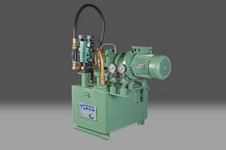
Hydraulic power pack : Some power packs are large, stationary units and others are more portable. They have a hydraulic reservoir, which houses the fluid, regulators that allow users to control the amount of pressure the power pack delivers to a valve, pressure supply lines and relief lines, a pump and a motor to power the pump.A hydraulic power network is a system of interconnected pipes carrying pressurized liquid used to transmit mechanical power from a power source, like a pump, to hydraulic equipment like lifts or motors. The system is analogous to an electrical grid transmitting power from a generating station to end-users. Hydraulic Power Unit Design and Operation. A hydraulic system employs enclosed fluid to transfer energy from one source to another, and subsequently create rotary motion, linear motion, or force. Hydraulic power units apply the pressure that drives motors, cylinders, and other complementary parts of a hydraulic system. Uses of power pack :

Yuken hydraulic pump shaft

Image
Shaft description :  A shaft is a rotating machine element, usually circular in cross section, which is used to transmit power from one part to another, or from a machine which produces power to a machine which absorbs power. The various members such as pulleys and gears are mounted on it. A is shaft used for : A drive shaft, driveshaft, driving shaft, propeller shaft (prop shaft), or Cardan shaft is a mechanical component for transmitting torque and rotation, usually used to connect other components of a drive train that cannot be connected directly because of distance or the need to allow for relative movement between them. There are two types of shaft:  1.Transmission Shaft :  Counter Shaft. The counter shaft lies parallel to the main shaft and is driven by the input shaft through a pinion gear. Output  Shaft . The final component that carries the power out of the   transmission   gearbox and on to the wheels is the output   shaft . 2.Machine Shaft

Yuken : Vane Pump

Image
Vane Pump : Vane pumps are available in a number of vane configurations including sliding vane (left), flexible vane, swinging vane, rolling vane, and external vane. Vane pumps are noted for their dry priming, ease of maintenance, and good suction characteristics over the life of the pump. Moreover, vanes can usually handle fluid temperatures from -32°C / -25°F to 260°C / 500°F and differential pressures to 15 BAR / 200 PSI (higher for hydraulic vane pumps). Each type of vane pump offers unique advantages. For example, external vane pumps can handle large solids.Flexible vane pumps, on the other hand, can only handle small solids but create good vacuum. Sliding vane pumps can run dry for short periods of time and handle small amounts of vapor. How Vane Pumps Work : Despite the different configurations, most vane pumps operate under the same general principle described below. 1. A slotted rotor is eccentrically supported in a cycloidal cam. The rotor is located cl

Yuken : Pressure relief valve

Image
 Pressure relief valve : Pressure relief valve  Dear friends today we are going to discuss about pressure relief valve : Pressure relief valve :  The purpose of a pressure relief valve is to control or limit surges of pressure within pipelines, acting as protection for the system, and defending against instrument or equipment failure. They are usually present in clean water industries. MGA Controls are experts in the specification and supply of Pressure Relief Valves for a wide range of industries and applications. Read on to find out more about the purpose of a pressure relief valve and pressure relief valve features.  The main purpose of a pressure relief valve is to protect life, environment and property. A pressure relief valve is a safety device, in numerous instances, the final safeguarding measure. It is important that the valve is maintained and operating at all times and under all circumstances.Pressure relief valve operation depends on the Singer  pilot

DEFINING SUCCESS - " GO KISS THE WORLD "

DEFINING SUCCESS - " GO KISS THE WORLD " Address by Subroto Bagchi, Chief Operating Officer, MindTree Consulting to the Class of 2006 at the Indian Institute of Management, Bangalore on Defining success.- July 2nd 2004 I was the last child of a small-time government servant, in a family of five brothers. My earliest memory of my father is as that of a District Employment Officer in Koraput, Orissa. It was and remains as back of beyond as you can imagine. There was no electricity; no primary school nearby and water did not flow out of a tap. As a result, I did not go to school until the age of eight; I was home-schooled. My father used to get transferred every year. The family belongings fit into the back of a jeep - so the family moved from place to place and, without any trouble, my Mother would set up an establishment and get us going. Raised by a widow who had come as a refugee from the then East Bengal, she was a matriculate when she married my Father. My parents se

YUKEN INDIA LIMITED

Image

Industrial

Image

YUKEN DIRECTIONAL CONTROL VALVE

Image
YUKEN DIRECTIONAL CONTROL VALVE DIRECTIONAL CONTROL VALVE OF YUKEN MAKE SOLONEOID OPERATED WITH VARIOUS SPOOL CONFIGURATION AVALIABLE AS LISTED BELOW DSG-01-2B2-R220-N1-50 DSG-01-2B2-D24-N1-50 DSG-01-2B2-A120-N1-50 DSG-01-2B2-A240-N1-50 DSG-01-2B2-D110-N1-50 DSG-01-2B2-A120-50 DSG-01-2B8-A240-50 DSG-01-2B2A-D24-N1-50 DSG-01-2B2A-A120-N1-50 DSG-01-2B2A-A240-N1-50 DSG-01-2B2B-D24-N1-50 DSG-01-2B2B-A120-N1-50 DSG-01-2B2B-A240-N1-50 DSG-01-2B3B-D24-N1-50 DSG-01-2B3B-A120-N1-50 DSG-01-2B3B-A240-N1-50 DSG-01-2B4B-D24-N1-50 DSG-01-2B3-A240-N1-50 DSG-01-2B3-D24-50 DSG-01-2D2-D12-N1-50 DSG-01-2D2-D24-N1-50 DSG-01-2D2-A120-N1-50 DSG-01-2D2-A240-N1-50 DSG-01-2D2-D110 DSG-01-2D2-D220 DSG-01-3C2-D24-N1-50 DSG-01-3C2-A120-N1-50 DSG-01-3C2-A240-N1-50 DSG-01-3C2-R220-N1-50